Calibration Access and Data Handbook


Next: Calling Parameters
Up: CAL_omDistortion
Previous: CAL_omDistortion
Contents
The routine returns the offset (deltaX, deltaY)
from the linear grid position for a specified detector location.
The linear grid position (linX, linY) is defined by the angular distance
to the OM boresight (i.e. pixel 1024.5,1024.5 in the V-filter),
divided by the platescale (section 3.5.8).
The input may consist of a list of positions.
The offset can be calculated in two different ways.
Either the offset is obtained by interpolation of the
coarsely mapped distortion or by direct evaluation of an up to 7th order
polynomial.
The way of calculation is selected by setting the input parameter calc_mode.
- If calc_mode is set to 0, then the distortion vector is calculated by
interpolation of the distortion map.
- If calc_mode is set to 1, then the distortion vector is calculated by
evaluation of the polynomial.
calc_mode is set to 0:
the distortion (deltaX, deltaY) at the detector location (rawX, rawY)
is derived from the distortion map stored in the extension
FILTER-FilterId (e.g. FILTER-U, FILTER-V, FILTER-GRISM1 etc.).
As the distortion map is only coarsly sampled an interpolation is required to
derive the distortion at the requested position
(rawX, rawY).
- select correct extension using the FilterId
- extract the n closest records around the specified detector
position (rawX, rawY)
e.g. (rawX
 ,rawY,RAWX_OFF,RAWY_OFF),
(rawX ,rawY,RAWX_OFF,RAWY_OFF), ...,
(rawX ,rawY,RAWX_OFF,RAWY_OFF).
with
- interpolate the extracted distortion points
(RAWX_OFF
 ,RAWY_OFF) and calculate the distortion
(deltaX,deltaY) at the requested postion (rawX, rawY)
,RAWY_OFF) and calculate the distortion
(deltaX,deltaY) at the requested postion (rawX, rawY)
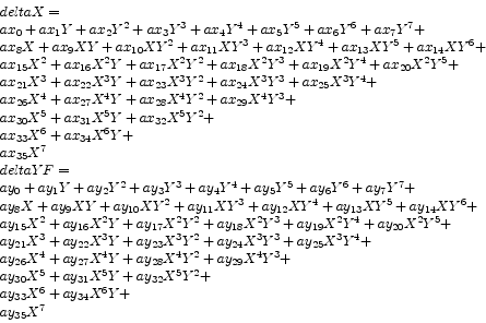
calc_mode is set to 1:
the distortion (deltaX,deltaY) at the location (rawX, rawY) is
computed using an up to 7th order polynomial.
The coefficients of the polynomials are stored in the
columns XPOLYCOEF, YPOLYCOEF of the extension POLYNOM_MAP.
Unused coefficients are set to zero in the CCF file, e.g. if only a second order polynomial
is used, then all higher order coefficients are zero.
There is one set of coefficients (XPOLYCOEF, YPOLYCOEF) per filter element
in the POLYNOM_MAP extension.
The required binary table entry is identified by matching the
value of the column FILTER_ID with the State Variable FilterID.
 |
(29) |
where
| deltaX, deltaY |
offset in x- and ydirection from linear grid. |
| |
The offset is defined as difference (true - linear) position |
| X |
offset from boresight in x-direction 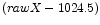 |
| Y |
offset from boresight in y-direction  |
 |
coefficients of the 7th order polynomial stored in the columns |
| |
XPOLYCOEF, YPOLYCOEF respectively. |
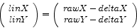
Interpretation of offset vector by SAS:
The offset vector (deltaX, deltaY) are used by the SAS to calculate the
angular distance of a position to the boresight in the following way.
First the linear offset (linX, linY) from the boresight
(in units of pixel) is calculated by the following equation:
 |
(30) |
Note that the offsets (deltaX, deltaY) are subtracted from the detector
coordinates (rawX, rawY), because the offsets are defined as the difference
between the measured and the expected (i.e. linear grid) position.
The angular separation from the boresight is defined as the linear offset
(linX, linY) divided by the platescale (section 3.5.8).
Next: Calling Parameters
Up: CAL_omDistortion
Previous: CAL_omDistortion
Contents
Michael Smith
2011-09-20