XMM-Newton
Users Handbook
3.3.1.2 EPIC pn chip geometry
The heart of the pn camera is a single Silicon wafer with 12 CCD chips
integrated. The pn chip array numbering scheme, the individual chip coordinate
frames and the directions of the detector coordinates are displayed in
Fig. 22.
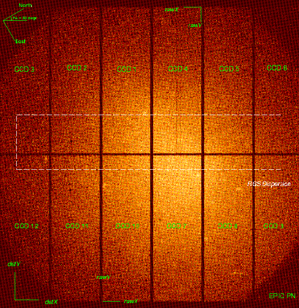
Figure 22:
The layout of the EPIC pn camera as presented in SAS.
The orientation of the RAWX/RAWY (CCD specific) and of the DETX/DETY axes
are shown, to highlight that the RGS dispersion axes are parallel within
spacecraft physical coordinates.
The readout CAMEX of each CCD is located at RAWY = 0, i.e. at the top
(for CCDs 1 - 6) or bottom (for CCDs 7 - 12) of the displayed array.
In the upper left corner, the orientation of the celestial North and East
axes is displayed for an assumed position angle (PA) of 30 .
.
 |
European Space Agency - XMM-Newton Science Operations Centre