Next: 5.2.4.5 Filling in OM exposures settings Up: 5.2.4 Entering exposure details Previous: 5.2.4.3 Filling in RGS details
Depending on the instrument mode in which observations are to be carried out, a few more options can be specified for RGS. These can be defined on a dedicated page which can be accessed by pressing the ”Edit Details” button at the bottom of the exposure page.
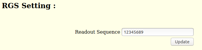
In the ”RGS Settings” form sheet, the only user-selectable parameter is the RGS CCD readout sequence.
For standard observations over the whole energy range this sequence
should not be changed. Only if users want to perform spectroscopy
over a part of the RGS bandpass or read out one or more chips
faster than others, a different sequence should be chosen.
Each RGS has 9 CCD chips, but is read out in a
cycle with up to 12 readout slots. The energy ranges covered by the
different RGS CCDs in different grating orders are described in the
XMM-Newton Users Handbook section 3.4.2 RFC arrays
![]() . If a user is interested in a particularly strong and scientifically
important line, falling for example in chip #3, and wants to
read this chip more often than all others, a readout sequence of, e.g., [3 1 2 3 4 5 3 6
3 8 9] could be chosen. This readout sequence implies that chip #3
will be read out 4 times more often than the others. Note that for RGS-1 and RGS-2 CCD 7 and CCD 4 are not available respectively.
. If a user is interested in a particularly strong and scientifically
important line, falling for example in chip #3, and wants to
read this chip more often than all others, a readout sequence of, e.g., [3 1 2 3 4 5 3 6
3 8 9] could be chosen. This readout sequence implies that chip #3
will be read out 4 times more often than the others. Note that for RGS-1 and RGS-2 CCD 7 and CCD 4 are not available respectively.
European Space Agency - XMM-Newton Science Operations Centre